

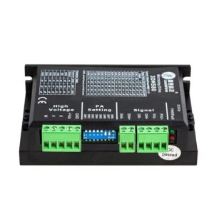
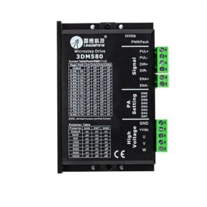
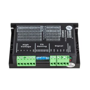
Step motor driver Leadshine 3DM580
Possibilities Leadshine 3DM580
|
 |
Specifications of stepper motor driver Leadshine 3DM580
| 3DM580 | Parameters | |||
| unit | max | normal mode | min | |
| A | 8.0 | – | 1.0 | Output Current |
| VDC | +50 | 36 | +18 | Voltage |
| mA | 16 | 10 | 7 | Logical signal flow |
| kHz | 500 | – | 0 | Pulse input frequency |
| MΩ | 100 | Insulation resistance | ||
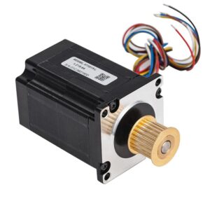
| NEMA 23, 34 | Suitable for stepper motors | |||
Photo

Mechanical specifications of stepper motor driver

Structure of stepper motor driver circuit Leadshine3DM580

Assignment pins and descriptions

details 3DM580 |
P1 Function |
| Pulse signal: In single pulse (pulse/direction) mode, this input represents pulse signal, each rising or falling edge active (software configurable);4-5V when PUL-HIGH, 0-0.5V when PUL-LOW. In double pulse mode (pulse/pulse) , this input represents clockwise (CW) pulse,active both at high level and low level (software configurable). For reliable response, pulse width should be longer than 2.5 us. Series connect resistors for current-limiting when +12V or +24V used. The same as DIR and ENA signals. | PUL+ |
| PUL- | |
| DIR signal: In single-pulse mode, this signal has low/high voltage levels, representing two directions of motor rotation; in double-pulse mode (software configurable), this signal is counter-clock (CCW) pulse,active both at high level and low level (software configurable). For reliable motion response, DIR signal should be ahead of PUL signal by 5 us at least. 4-5V when DIR-HIGH, 0-0.5V when DIR-LOW. Please note that rotation direction is also related to motor-driver wiring match. Exchanging the connection of two wires for a coil to the driver will reverse motion direction. | DIR+ |
| DIR- | |
| Enable signal: This signal is used for enabling/disabling the driver. High level (NPN control signal, PNP and Differential control signals are on the contrary, namely Low level for enabling.) for enabling the driver and low level for disabling the driver. Usually left UNCONNECTED (ENABLED). | ENA+ |
| ENA- |
|
P2 Function |
3DM580 Details |
|
GND |
Power Ground |
|
+Vdc |
Power supply, 18~50 VDC, Including voltage fluctuation and EMF voltage. |
|
U |
Motor phase U |
|
V |
Motor phase V |
|
W |
Motor phase W |


Reviews
There are no reviews yet.